 Here in Wise Labs there are
ongoing results for a encumbrance design of Lander Modules. So here is a small
experimental electric thrusters, in which power is supplied via
Electron-Cyclotron Resonance (ECR) absorption of microwaves by the propellant
gas, has been tested by NASA Marshall Space Flight Centre (MSFC). The plasma
generated is confined radials by an axial dc magnetic field applied through a
series of water-cooled coils around the resonance chamber. The B-field is
maintained at about the strength required for ECR in the central part of the
chamber (the ECR zone), with stronger magnetic fields acting as magnetic Gas
Dynamic Mirrors (GDM) at the ends. The plasma is ejected into the vacuum
chamber through the downstream magnetic mirror, which acts as a magnetic
nozzle. Of the magnetic field configurations tested, the one most similar to
the GDM device proposed by wise labs produced the most significant results.
Here in Wise Labs there are
ongoing results for a encumbrance design of Lander Modules. So here is a small
experimental electric thrusters, in which power is supplied via
Electron-Cyclotron Resonance (ECR) absorption of microwaves by the propellant
gas, has been tested by NASA Marshall Space Flight Centre (MSFC). The plasma
generated is confined radials by an axial dc magnetic field applied through a
series of water-cooled coils around the resonance chamber. The B-field is
maintained at about the strength required for ECR in the central part of the
chamber (the ECR zone), with stronger magnetic fields acting as magnetic Gas
Dynamic Mirrors (GDM) at the ends. The plasma is ejected into the vacuum
chamber through the downstream magnetic mirror, which acts as a magnetic
nozzle. Of the magnetic field configurations tested, the one most similar to
the GDM device proposed by wise labs produced the most significant results.

 The Radio Frequency (RF)
waves, or microwaves, that power the thrusters, are launched axially into the
resonance chamber and couple very strongly with the argon plasma. Electron
densities of 10^11 to 10^13 per cm^3 have been measured in the plume downstream
of the magnetic nozzle. Bi-modal velocity profiles have been measured within its
plume via Laser Induced Fluorescence (LIF).
The Radio Frequency (RF)
waves, or microwaves, that power the thrusters, are launched axially into the
resonance chamber and couple very strongly with the argon plasma. Electron
densities of 10^11 to 10^13 per cm^3 have been measured in the plume downstream
of the magnetic nozzle. Bi-modal velocity profiles have been measured within its
plume via Laser Induced Fluorescence (LIF). An experimental electric thrusters
has been built for testing at the NASA Marshall Space Flight Center (MSFC).

The
plasma is formed by Electron-Cyclotron Resonance (ECR) absorption of microwaves
at 10.1 GHz frequency. The plasma is confined radials (the at pitch) by an
applied axial dc magnetic field, with a strength of 0.36 tesla (3600 gauss) for
ECR. The field is shaped by a strong magnetic mirror on the upstream end and a
magnetic nozzle on the downstream end. An argon gas is used as the test
propellant, although a variety of gases may be utilized preferring natural induced
ion plasma. The drilling core using the standard model Higgs,
Laser Drilling or drilling is to cut a hole around its
periphery by moving the work-piece with an xy-table or the beam with a suction pressure removal can use varied designs head. The speed of drilling is dictated by the material removal rate
and the relative laser/work-piece moving speed. It is possible to trepan holes
with one or more circles to improve the hole quality or to produce holes in
thick materials. For high throughput drilling or drilling of conical holes. although Wise Labs Is demonstrating moving a bore at very high speeds with minimum back draft these designs are to be published with a flexible wall mix fixing.
Wise Lab using Alice techniques for tunnelling uses a laser mole these heads using galvanometer scanners, off-axis rotating lenses or
rotating wedge prisms are used. In this case, the focused laser beam is rotated
at very high rates (up to 40,000 rpm) around a centre point and exactly
describes the hole geometry. Holes drilled by taring all the way trough embedding the wall are cleaner on their
edges. Both hole roundness and hole diameter’s reputability are high. mounted either a spider robot or a side-ward tank unit drive refuel able h20 rocket platform
 Here in Wise Labs there are
ongoing results for a encumbrance design of Lander Modules. So here is a small
experimental electric thrusters, in which power is supplied via
Electron-Cyclotron Resonance (ECR) absorption of microwaves by the propellant
gas, has been tested by NASA Marshall Space Flight Centre (MSFC). The plasma
generated is confined radials by an axial dc magnetic field applied through a
series of water-cooled coils around the resonance chamber. The B-field is
maintained at about the strength required for ECR in the central part of the
chamber (the ECR zone), with stronger magnetic fields acting as magnetic Gas
Dynamic Mirrors (GDM) at the ends. The plasma is ejected into the vacuum
chamber through the downstream magnetic mirror, which acts as a magnetic
nozzle. Of the magnetic field configurations tested, the one most similar to
the GDM device proposed by wise labs produced the most significant results.
Here in Wise Labs there are
ongoing results for a encumbrance design of Lander Modules. So here is a small
experimental electric thrusters, in which power is supplied via
Electron-Cyclotron Resonance (ECR) absorption of microwaves by the propellant
gas, has been tested by NASA Marshall Space Flight Centre (MSFC). The plasma
generated is confined radials by an axial dc magnetic field applied through a
series of water-cooled coils around the resonance chamber. The B-field is
maintained at about the strength required for ECR in the central part of the
chamber (the ECR zone), with stronger magnetic fields acting as magnetic Gas
Dynamic Mirrors (GDM) at the ends. The plasma is ejected into the vacuum
chamber through the downstream magnetic mirror, which acts as a magnetic
nozzle. Of the magnetic field configurations tested, the one most similar to
the GDM device proposed by wise labs produced the most significant results.
 The Radio Frequency (RF)
waves, or microwaves, that power the thrusters, are launched axially into the
resonance chamber and couple very strongly with the argon plasma. Electron
densities of 10^11 to 10^13 per cm^3 have been measured in the plume downstream
of the magnetic nozzle. Bi-modal velocity profiles have been measured within its
plume via Laser Induced Fluorescence (LIF). An experimental electric thrusters
has been built for testing at the NASA Marshall Space Flight Center (MSFC).
The Radio Frequency (RF)
waves, or microwaves, that power the thrusters, are launched axially into the
resonance chamber and couple very strongly with the argon plasma. Electron
densities of 10^11 to 10^13 per cm^3 have been measured in the plume downstream
of the magnetic nozzle. Bi-modal velocity profiles have been measured within its
plume via Laser Induced Fluorescence (LIF). An experimental electric thrusters
has been built for testing at the NASA Marshall Space Flight Center (MSFC).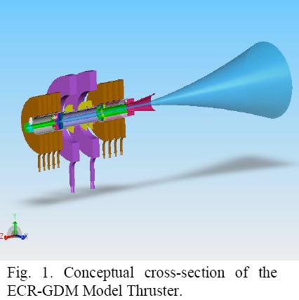 The
plasma is formed by Electron-Cyclotron Resonance (ECR) absorption of microwaves
at 10.1 GHz frequency. The plasma is confined radials (the at pitch) by an
applied axial dc magnetic field, with a strength of 0.36 tesla (3600 gauss) for
ECR. The field is shaped by a strong magnetic mirror on the upstream end and a
magnetic nozzle on the downstream end. An argon gas is used as the test
propellant, although a variety of gases may be utilized preferring natural induced
ion plasma. The drilling core using the standard model Higgs, Laser Drilling or drilling is to cut a hole around its
periphery by moving the work-piece with an xy-table or the beam with a suction pressure removal can use varied designs head. The speed of drilling is dictated by the material removal rate
and the relative laser/work-piece moving speed. It is possible to trepan holes
with one or more circles to improve the hole quality or to produce holes in
thick materials. For high throughput drilling or drilling of conical holes. although Wise Labs Is demonstrating moving a bore at very high speeds with minimum back draft these designs are to be published with a flexible wall mix fixing.
The
plasma is formed by Electron-Cyclotron Resonance (ECR) absorption of microwaves
at 10.1 GHz frequency. The plasma is confined radials (the at pitch) by an
applied axial dc magnetic field, with a strength of 0.36 tesla (3600 gauss) for
ECR. The field is shaped by a strong magnetic mirror on the upstream end and a
magnetic nozzle on the downstream end. An argon gas is used as the test
propellant, although a variety of gases may be utilized preferring natural induced
ion plasma. The drilling core using the standard model Higgs, Laser Drilling or drilling is to cut a hole around its
periphery by moving the work-piece with an xy-table or the beam with a suction pressure removal can use varied designs head. The speed of drilling is dictated by the material removal rate
and the relative laser/work-piece moving speed. It is possible to trepan holes
with one or more circles to improve the hole quality or to produce holes in
thick materials. For high throughput drilling or drilling of conical holes. although Wise Labs Is demonstrating moving a bore at very high speeds with minimum back draft these designs are to be published with a flexible wall mix fixing. 


No comments:
Post a Comment